Network Diagrams: The Significance of Comprehensive Network Overview Documentation
BY IT GLUE | November 02, 2021
Any IT network consists of multiple interconnected devices that share resources and enable seamless transfer of information. To gain a deeper knowledge of dense networks, it is extremely important to visualize them with the right representation of various components. Network diagramming can help you with that and more. With robust network documentation software, you can get an in-depth look at your networks and understand the connections in your data.
What Is a Network Diagram?
A network diagram provides a visual representation of how a computer or telecommunications network works. It visually depicts the various components that make up a network, including routers, devices, hubs, and firewalls, and how they interact with each other. Considering the different interdependencies in any given network, these diagrams use graphics to visually represent these dependencies and interdependencies.
What is a network diagram used for?
A network diagram eliminates guesswork when it comes to troubleshooting network configurations. It provides a visual illustration of how different network components are related to each other. Technicians can use this information to save valuable resources, such as money and time, when working on a network. The visual display of various components working seamlessly can help identify specific areas where errors or problems occur.
What are the benefits of network diagrams?
There are several benefits to having network diagrams for your IT network.
- Organizations cannot afford lengthy downtime for maintenance in today’s competitive scenario. With a reliable network diagram, you can quickly sort out network issues and get back online.
- Network diagrams can also help increase efficiency as it eliminates the time wasted by technicians on identifying the source of an issue.
- Since all components are identified in a network, you can use this information to plan, organize and control the workflow in your network. When executing major tasks, you can use this illustration to get them done efficiently.
What Should a Network Diagram Include?
A general network diagram can provide a high-level perspective of your network as well as a more specific description. A comprehensive diagram will include more information while a general diagram will have a cleaner layout with only the most important framework.
What are the components of a network diagram?
Creating a network diagram starts with listing out the components you are likely to use. The key here is to not leave out any network components. Some of the key components include the following:
- Workstations & PCs
- Servers
- Mainframes
- Mobile devices
- Routers
- Printers
- Scanners
- Firewalls
- Switches
- Hubs
- Modems
What Are the Different Types of Network Diagrams?
From simple hand-drawn pictures to sophisticated software illustrations, network diagrams can vary a lot from one to another. A typical network diagram contains various lines and nodes that are represented by different icons.
If you wish to have an accurate network diagram, you need to understand the underlying topologies of the network. Topologies refer to how different network components are arranged. Based on this, we can categorize network diagrams.
Logical vs. Physical Network Diagrams
Irrespective of how sophisticated they are, network diagrams can either be logical or physical. This categorization concerns how various devices are arranged in a network.
Logical Network Diagrams
These are the most commonly used diagrams by network administrators since these diagrams provide information about the flow of data in a network. This depicts how devices communicate with one another and how information flows through a network. Components like subnets, network objects and devices, routing protocols and domains, voice gateways, traffic flow, and network segments are typically displayed here.
Physical Network Diagrams
As the name implies, this shows the physical arrangement of a network. In a sense, it is similar to that of a floor plan. All physical aspects including cables, ports, racks, servers and any other hardware or devices are displayed in these diagrams. This view helps administrators get a bird’s eye view of all that is happening in a network.
Network Topology Diagrams
The arrangement of physical or logical elements in a network is known as topology. There are different derivations of topology in a network. Some of these derivations are better applied for logical diagrams while others are better for physical diagrams.
Let’s check out some of the common topologies used in network diagrams and the type of mapping best suited for them.
Bus Topology Diagrams
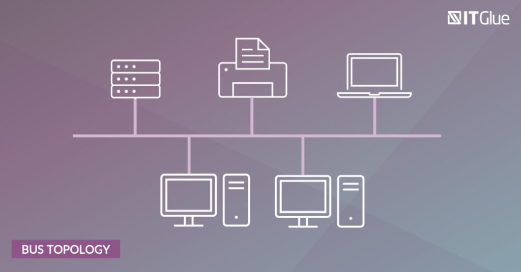
This is also known as the linear topology diagram and is the simplest one on the list. Here, all devices are connected with the help of a single cable, also known as a bus. Although this is easy to set up and inexpensive, the entire network is vulnerable to a shutdown without any prior warning. Hence, it is ideal for small networks with a limited number of devices.
Ring Topology Diagrams

In this network topology diagram, devices are connected in a circular model in the shape of a ring. During data transmission, the packets travel through the ring to reach their destination. While bi-directional ring topologies are possible, most ring networks are unidirectional – meaning data packets can travel in only one direction. This is still vulnerable to total network shutdown even if one workstation is impacted.
Star Topology Diagrams

This contains a central hub that connects to all components in a network. Data passes through the hub when transmitted from one device to another. Due to its central management, it is easy to add new devices to the network. Also, it provides better reliability as the shutdown of a single device will not affect the whole network. However, it is still vulnerable to shutdown if the central hub is affected.
Mesh Topology Diagrams

In this type of topology, all devices in the network are interconnected with one another. This ensures seamless distribution of data packets even if one of the devices or connections goes down. This topology is typically used in wireless networks.
Point-to-Point (P2P) Topology Diagrams

This topology connects any two devices in a network with a common link. The devices can be any component in a network. For instance, a workstation can be connected to a router with the help of a cable in this topology.
Tree Topology Diagrams

This hybrid topology resembles the structure of a tree in the way in which the devices are connected. It is one of the simplest models in the sense that it has only one route between any two nodes in the network. It is flexible and easy to scale. Hence, it is widely used in various large networks.
Network Diagramming Made Easy With IT Glue & Network Glue
As one of the top players in cloud-based IT documentation, IT Glue can help you with seamless network discovery, diagramming and documentation. IT Glue’s Network Glue solution equips you with the right tools required to generate comprehensive network diagrams with automated network discovery, documenting and diagramming that is always up to date.
IT Glue’s SOC 2-compliant documentation platform features an immutable audit trail, multifactor authentication and next-generation password management engine, all of which are fully integrated and linked with all your network documentation.
To learn more about how IT Glue and Network Glue can help with network diagramming, request a demo.
Found this article helpful? Share it with your social network using the icons below.
